RFT Plot
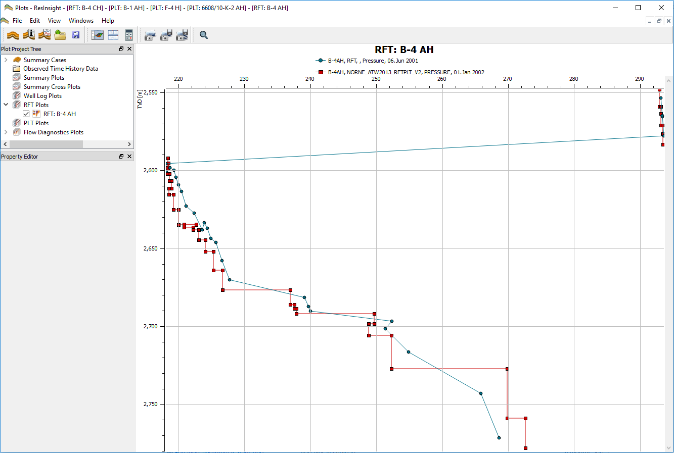
An RFT (Repeated Formation Tester) plot is a special well plot for comparing observed formation pressure and simulated formation pressure. The curves are plotted as pressure against true vertical depth (TVD) or measured depth (MD). Simulated pressure data is retrieved directly from the grid model or from the corresponding (*.rft) files, while observed pressure data are loaded from well log files (*.las).
Create New RFT Plot
There are several ways to create new RFT Plots.
- From the Project Tree in the Plot Main Window
- Select right-click command New RFT Plot for Well Path node or RFT Plots node.
- From the Project Tree in the 3D Main Window
- Select right-click command New RFT plot for a simulation well.
- From a 3D view
- Right-click a simulation well select Well Plots -> New RFT Plot.
Create Multiple RFT Plots
ResInsight can automate the creation of multiple plots based on an already existing RFT plot.
Description of the workflow:
- create a RFT plot for one well
- on the right-click menu of this plot, select Create Multiple RFT Plots
- a list of available wells is displayed, and the user can select the wells
- click OK, and the plots for selected wells are created
Import Observed RFT Data
Pressure Depth Data
A custom file format for Pressure Depth Data is supported.
LAS Pressure Data
To be able to plot observed pressure data for a well in an RFT plot, at least one well log file from that well (e.g. *.las) has to be imported to ResInsight. This file must contain a pressure column, which must have the name PRESSURE or PRES_FORM. If the well log file itself does not contain a TVD column (named TVDMSL), a well path file (See Well Trajectories) for the same well must also be imported to ResInsight.
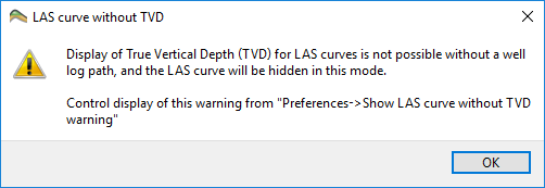
If no TVD data for a well is found when the user tries to plot a curve, ResInsight will present a warning dialog to the user.
Property Editor
The property editor lets the user select which curves to display in the RFT plot.
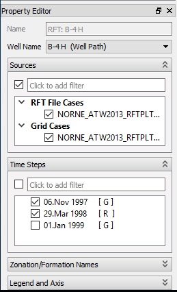
Well Name
Select the well to display in the plot. Wells postfixed by ’(Well Path)’ have an associated well trajectory loaded.
Sources
After a well has been selected in the Well Name field, the relevant sources for that well will appear in the sources field. The sources are placed in one of three different groups:
- RFT File Cases – Simulation cases may have associated formation pressure data in *.rft file(s). If the simulation case contains such files, those are imported together with the simulation case (See the keyword
WRFTPLTfor more information). - Grid Cases – The PRESSURE property in the 3D grid.
- Observed Cases – Observed data imported from well log files.
When the user selects one or more sources, a selection of their time steps appears in the Time Steps field.
Time Steps
The Time Steps field contains the relevant time steps according to the source selection. Time steps are deemed to be relevant by the following rules:
- If a single source or sources of the same type are selected, all available time steps in those sources are shown.
- If sources from two or tree types are selected, the time steps are filtered:
- The time steps matching the observed case(s) time steps.
- If no time steps from a case match the observed time step, the two adjacent ones are shown.
- The first time step from any grid case(s) (as initial pressure reference). If the Observed data isn’t selected, the RFT data serves as filter reference.
Each time step is postfixed by an indication of which source type(s) the time step is belonging to. This indication is displayed as one or more letters within square brackets. Examples: [ O ], [ R G ].
- O – Time step has observed data
- R – Time step has RFT data
- G – Time step has Grid data
More than one letter for one single time step, means that the time steps comes from multiple case types.
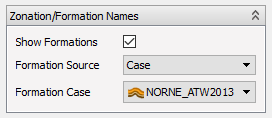
Zonation/Formation Names
This property editor lets the user control the visibility of formations lines. This is what it looks like in the RFT plot context.
Please see the full documentation on the formations property editor for details about formations.
Note
When the formation names property editor is used in the context of RFT plots, the fields Trajectory and Simulation Well are hidden because those values are given by the RFT plot definition.
Legend and Axis
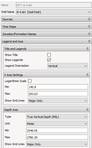
This property editor lets the user control visual properties for the legend and axis.
- Title and Legends
- Show Title – Toggle on/off title in plot
- Show Legends – Toggle on/off legend in plot
- Legend Orientation – Vertical or horizontal
- X Axis Settings
- Logarithmic Scale – Toggle between linear and logarithmic
- Min – Set X axis minimum value
- Max – Set X axis maximum value
- Show Grid Lines – Enable grid lines in background in plot
- Depth Axis
- Type – Toggle between True Vertical Depth (MSL) or Measured Depth (MD)
- Unit –
- Min – Set depth axis minimum value
- Max – Set depth axis maximum value
- Show Grid Lines – Enable grid lines in background in plot