Completions
Three types of completions are available for modeling and export: Perforation intervals, Fishbones® wells and fractures. The purpose of modeling these completions, is that it enables ResInsight to export Eclipse keywords for doing more refined simulations.
Completions can be modeled by adding new perforation intervals, fishbones subs or fractures. Details about the completions must then be specified, such as the length of the perforation interval or number of fishbone subs and laterals. After modeling the completions, the transmissibility (cell connection factors) can be calculated and exported to the Eclipse COMPDAT Keyword. See Export Completions
For fishbones completions, multi-segment well information can even be exported to the Eclipse Keywords WELSEGS, COMPSEGS and WSEGVALV, c.f. Export Well Segments.
Note
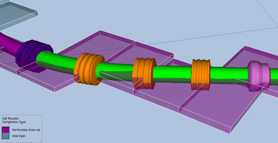
The derived cell property Completion Type displays which cells are intersected by the completions.
Visualization and Inspection of Well Connection Factors
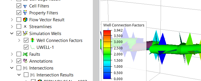
Connection factors both from the Simulation Wells and the ones calculated from the modeled completions can be visualized in the 3D view by enabling Well Connection Factors in the Project Tree. The connection factors are displayed with a symbol as in the example shown above. The color of the symbol displays the magnitude of the connection factor and can be controlled by the legend settings. Additional details of the connection factor are displayed in the Result Info window when clicking on the connection factor symbol.
The Property Panel of the Well Connection Factors item has a few options:
- Geometry Scale Factor – Scales the connection factor symbols relative to the displayed well path radius
- Show on Closed Connections – Show the connection factors calculated for closed simulation well cells in addition to the ones at open cells.
A combined view of well connection factors and the derived result Completion Type enables the user to see the completion type contributing to connection factor in a cell.
Perforation Intervals
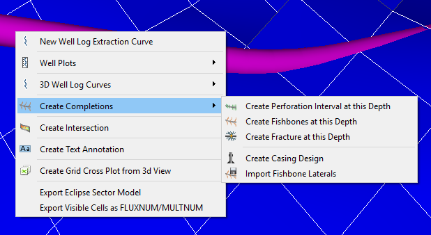
A new perforation interval on a well can be set up by right-clicking on the well in the 3D View or in the Project Tree, and choosing the command Create Perforation interval in the Create Completions sub-menu. In the 3D View the completion will be created at the specific depth the right-click occurred at.
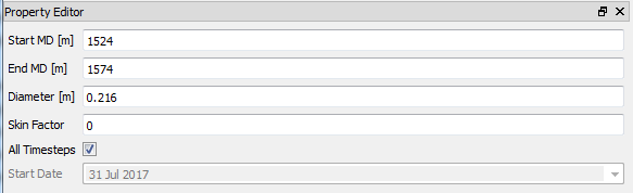
After creating the perforation interval, the following properties of the perforation can be set in the property editor:
- Start MD, End MD – Measured depth along the well path for the perforation to start/stop.
- Diameter – Well bore diameter for the perforation interval, used in calculation of transmissibility ( For details on the transmissibility calculation, see Transmissibility Calculations).
- Skin Factor – Skin factor for the perforation, used in calculation of transmissibility.
- All Timesteps – If on, the perforation interval will be present for all time steps
- Start Date – The perforation will be included in the model for all time steps after this date. If “All TimeSteps” is turned on, this option is not available and the perforation is included for all time steps.
The perforation intervals will be indicated by different color along the well path.
For each well path there is a top level folder in the Project Tree containing all the perforation intervals definitions containing settings that applies to all the perforation intervals for this well path.
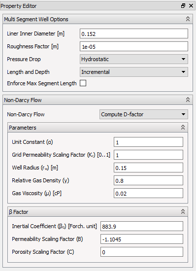
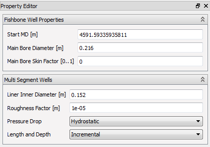
For multi-segment wells there are additional parameters which should be set. These are used in the export of WELSEGS data.
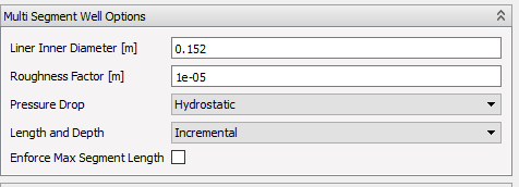
- Multi Segment Well Options - Options used by the Well Segments Export
- Liner Inner Diameter – The liner inner diameter for the completion intervals.
- Roughness Factor – The roughness factor used in export of main bore segments.
- Pressure Drop – can be either Hydrostatic, Hydrostatic + Friction or Hydrostatic + Friction + Acceleration.
- Length and Depth – Used in WELSEGS export - when specifying the length and depth change for each segment
- Incremental – length / depth of given segment
- Absolute – the length down the tube or depth of the last nodal point
- Enforce Max Segment Length – Limit segment to max size. When this check box is checked, a max segment length input field is displayed.
There are three options for Non-Darcy Flow. None, User defined D-factor and Compute D-factor. The second option displays an input field where the user defined D-factor can be entered. The last options calculates D-factor for gas using a radial inflow model and correlation for calculating matrix beta factor depending on permeability and porosity (LP Dake 1976).
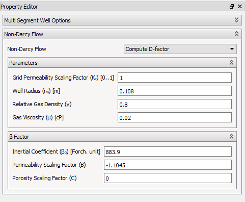
- Non-Darcy Flow - Non-Darcy settings for D factor computation
- Grid Permeability Kr Scaling Factor – Rel.perm. scaling factor to calculate effective permeability.
- Well Radius – Well bore radius.
- Relative Gas Density
- Gas Viscosity – Gas viscosity at flowing bottom hole pressure.
- Inertial Coefficient – Coefficient to calculate beta factor.
- Permeability Scaling Exponent – For beta factor calculation.
- Porosity Scaling Exponent – For beta factor calculation.
Perforation Interval Valves
Perforation Intervals can have valves (ICDs/AICDs/ICVs) associated with them.
These valves can be created by right-clicking on the Perforation Interval and selecting Create Valve.
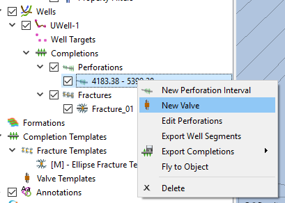
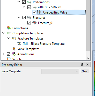
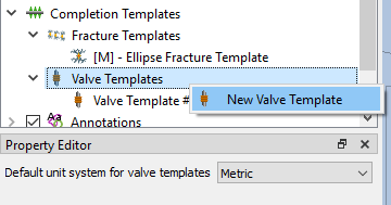
Each Valve require a Valve Template containing properties which can be shared among multiple Valves. If you have no Valve Template, a new one can be created by clicking the New button next to the Valve Template selection list.
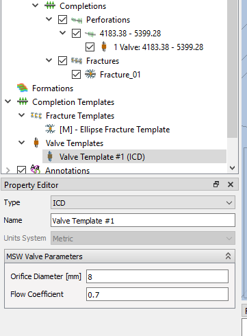
This will create a new Valve Template which can be of four different types:
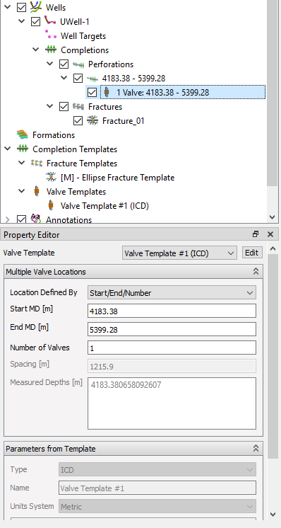
- ICD - In-flow Control Device, allowing the setting of Orifice Diameter and Flow Coefficient. ICDs are displayed in Orange.
- AICD - Autonomous In-flow Control Device, providing several more parameters associated with the Eclipse simulation and seen in the picture below. AICDs are displayed in Dark Purple.
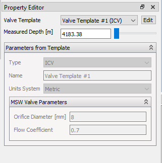
- ICV - Interval Control Valves. Contains the same parameters as ICDs. The difference between the two in ResInsight is that many ICDs can be added at the same time, while there is only expected to be one ICV per perforation interval. ICVs are displayed in Pink.
- SICD - Spiral Inflow Control Device. A passive inflow control device that provides flow resistance based on fluid properties, including emulsion behavior. Exported to the Eclipse WSEGSICD keyword. SICDs are displayed in Cyan.
An example of the ICD parameters can be seen below:
An example of the AICD parameters:
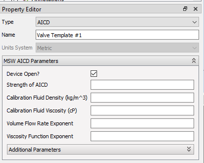
AICD valves can be imported from Completor or Eclipse text files from the right-click menu of Valves.
The SICD parameters are set in a group called MSW SICD Parameters:
- Device Open – Whether the SICD device is open or shut.
- Strength – The strength (flow resistance) of the SICD device.
- Calibration Fluid Density – Density of the calibration fluid used to characterize the device.
- Calibration Fluid Viscosity – Viscosity of the calibration fluid.
- Local Water in Liquid Fraction (EMLCRT) – Critical water-in-liquid fraction at which the emulsion viscosity model transitions.
- Width of Transition Zone (EMLTRNS) – Width of the transition zone in the emulsion viscosity function.
- Max Emulsion Viscosity to Cont Phase Viscosity (EMLMAX) – Maximum ratio of emulsion viscosity to continuous-phase viscosity.
- Max Surface Flow Rate (CALRATE) – Maximum surface flow rate used in calibration.
New templates can also be added by selecting the New Valve Template option from the right-click menu of the Valve Templates entry in the Completion Templates Project Tree item.
For ICDs and AICDs, multiple valves can be added in the same go by specifying the number of valves, spacing of valves or specific positions of valves as chosen in the Location Defined By drop down list.
For ICVs only one valve is added at a time so only the measured depth of that valve can be chosen.
When you have a valid valve template selected, there is an Edit button next to the valve template selection. Clicking this will take you straight to modify the valve template.
Import Perforation Intervals
Perforation intervals can be imported into ResInsight from *.ev files. These files consist of a list of wells, and their corresponding measured depth values for perforation start and end.
Perforation Interval File Format
“–” is interpreted as the start of a comment. The comment ends at the end of the line. The files can start with a unit definition line:
UNITS <unitname>
Info
This line is ignored for now. The numbers are interpreted to be in the units present in the case.
In the following any number of :
WELLNAME <well-name>
<date>  <well completion>  <top mMD>  <base mMD>   <bore hole diameter>  <skin factor>
<date>  <well completion>  <top mMD>  <base mMD>   <bore hole diameter>  <skin factor>
- date – Start date of the completion in the format “dd mmm yyyy”. Eg
01 SEP 2006. A special"SOH"date is also allowed meaning Start Of History. - well completion – For now, only
"perforation"is supported
Here is an example:
UNITS METRIC

-- R-2 AH sidetrack into Ile/Tilje
WELLNAME R-2AH
"SOH"   perforation 6200 6350 0.212 0   -- target Ile 2 and Ile 3
"SOH"   perforation 7050 7133 0.212 0   -- target Tilje 3, 83 m prodint

-- S-2 AH
WELLNAME S-2AH
"SOH"   perforation 4340 4369 0.212 0   -- target Garn 2, 29 m prodint (update 290915)
01 SEP 2006   perforation 5060 6185 0.212 0   -- target Tilje 3, 1125 m prodint
Fishbones
Fishbones are completions created by drilling or by jetting a set of small lateral holes with a high deviation from the main bore. Each set of holes created at the same location along the main bore, is referred to as a sub while each individual hole is called a lateral.
For each well path there is a top level folder in the Project Tree containing all the Fishbones definitions containing settings that applies to all the fishbones for this well path. To make use of the Multi Segment Well option for pressure loss along laterals, the grid resolution needs to be fine enough to allow a grid cell to be connected to only one lateral.
- Fishbone Well Properties – Settings used when exporting well connection factors
- StartMD – the start position for the fishbones. This will be set to the highest possible value automatically, but can be set lower by the user. Gives the point along the well from which the transmissibility from the matrix to the main bore will be calculated.
- Main Bore Diameter – The hole diameter for the main bore will be used in the calculation of the transmissibility (connection factor) into the main bore.
- Main Bore Skin Factor – The skin factor for the main bore, used in calculation of the transmissibility (connection factor) into the main bore. For multi-segment wells there are additional parameters which should be set. These are used in the export of WELSEGS data.
- Multi Segment Wells - Options used by the Well Segments Export
- Liner Inner eter – The liner inner diameter for the fishbones.
- Roughness Factor – The roughness factor used in export of main bore segments.
- Pressure Drop – can be either Hydrostatic, Hydrostatic + Friction or Hydrostatic + Friction + Acceleration.
- Length and Depth – Used in WELSEGS export - when specifying the length and depth change for each segment
- Incremental – length / depth of given segment
- Absolute – the length down the tube or depth of the last nodal point
Fishbones Subs Definition
To add new fishbones completions, select the New Fishbones Subs Definition command. This menu item is available by right clicking on Wells in the Project Tree or right clicking on the well trajectory in the 3D View.
The new Fishbones Subs Definition (a group of fishbone subs) is created in the Project tree. Several subs definitions can be created on the same well trajectory to give more flexibility in placing of the fishbones. The default sub definition is based on the Fishbones Drilling System with 3 laterals exiting per sub in a 8 1/2" main bore.
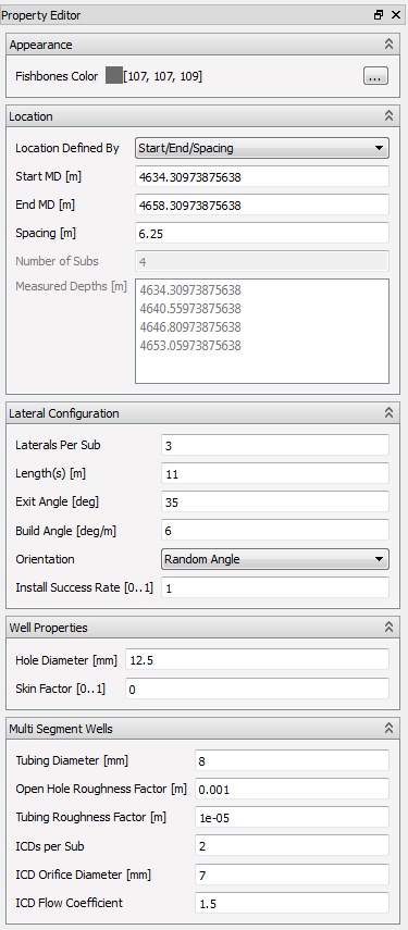
- Appearance
- Fishbones Color – The 3D View color of the fishbones created by this definition
- Location – Options to control the position and number of fishbone subs created by this definition
- Location Defined By – This setting will select how to define the location of the subs in this group.
- Start MD – Position, in Measured depth along the well, of the first fishbone Sub.
- End MD – Position of the last fishbone Sub.
- Number of Subs – Defines the number of subs to create in the defined interval
- Spacing – Spacing between the subs within the interval
- Measured Depths – The measured depth of each of the fishbone subs. If the Location Defined By is set to the User Specified this will be directly editable by the user.
- Laterals Configuration – Configures the laterals at each sub position.
- Laterals Per Sub – Number of laterals for each sub position
- Length(s) – Length of each lateral, in m or ft.
- Exit Angle – Exit angle for fishbone lateral, in degree.
- Build Angle – Build angle for fishbone lateral, in degree pr meter.
- Orientation
- Fixed Angle – The user can specify the angle for the first lateral
- Random angle – Each sub will have a random orientation. Notice that the angle between each of the laterals will be constant, with the laterals equally spaced.
- Install Success Rate – Gives the probability of success for installation of each of the fishbones laterals. If 1, all laterals are installed.
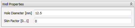
- Well Properties – Settings to control the connection factor calculation used in Completion Export)
- Hole Diameter – The hole diameter of the lateral
- Skin Factor – The skin factor used in the transmissibility calculation for the lateral.
- Multi Segment Wells – Settings used for Well Segment Export
- Tubing Diameter – The diameter used in the WELSEGS export of the laterals.
- Open Hole Roughness Factor – Exported directly to the WELSEGS keyword.
- Tubing Roughness Factor – Exported directly to the WELSEGS keyword.
- ICDs per Sub – The number of ICD (valves) per Sub, used for calculation of total ICD area for WSEGVALV export.
- ICD Orifice Diameter – The Diameter of the ICD, used for calculation of ICD area for WSEGVALV export.
- ICD Flow Coefficient – The flow coefficient, exported directly as a part of WSEGVALV.
Import Well Trajectories as Fishbones Laterals
The command Import Completions From File can be used to import well trajectories in the *.dev format as fishbone laterals. The imported laterals are listed under the folder Imported Laterals in the Project Tree. These laterals behave as completions, and will be exported when exporting completion data using the settings in the property panel of the Imported Laterals folder.
Export Fishbones as Well Trajectories
The Export Laterals command will export the fishbone laterals as a well trajectory into a *.dev* -file.
Info
Notice that only the trajectory data is exported. Properties related to well segment data or Completion Data export can not be written to .dev files.
Fractures
Hydraulic fractures are completions created by pressurizing the reservoir at a certain point in the well, and thereby creating a crack in the formation. A substance is then injected into the crack to keep it open when relaxing the pressure.
Fractures in ResInsight can be Well Trajectories, and have two main types: Elliptical fractures and StimPlan™ fractures.
Visualization control
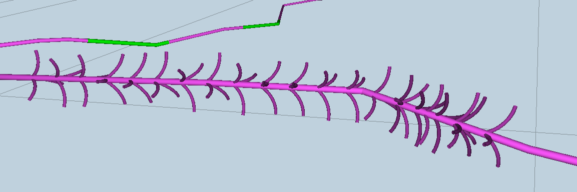
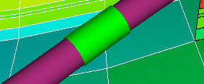
The Fractures item in the Project Tree controls whether to show the modeled fractures or not. For fractures along the well path the Perforation Length is shown as an olive green cylinder around the well path as shown in the image below.
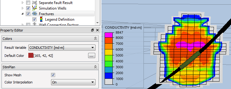
- Colors – Control the color settings for the fractures in the View
- Result Variable – Selects the fracture result to use for coloring the fracture. This is most interesting when you have imported a StimPlan fracture with varying width, conductivity and other parameters. The legend item in the Project Tree controls how the legend is set up.
- Default Color – The color to use if the requested result is not available for some fracture.
- StimPlan
- Show Mesh – Toggles the visualization of the StimPlan mesh lines, showing the StimPlan cell borders
- Color Interpolation – Toggles interpolation of the StimPlan results. When Off, one color per StimplanCell is shown. When on, ResInsight interpolates the color between the cells.
Fracture Templates
To create a functioning fracture you first need a Fracture Template. The template collects settings that are likely to be shared among several fractures, most importantly the fracture geometry. A fracture at a particular place refers to the template, and it is thereby possible to share fracture geometry and other settings between fracture instances.
Fracture Templates are listed in a folder with the same name in the Project Tree.
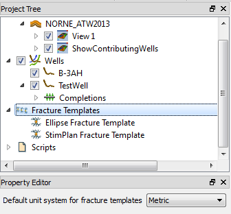
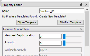
To create a new fracture template, right-click the Fracture Template item in the tree, and select either New Ellipse Fracture Template or New StimPlan Fracture Template. If you have no existing fracture templates, you will be given the opportunity to create such templates through two buttons in the Fracture Property Editor as seen below.
Common Fracture Template Options
- Name – User defined name for the template. Used when selecting which template to use in the Fracture
- ID – Assigned ID to be used when addressing this template form a Command file script
- Geometry
- Fracture Orientation – The fractures orientation
- Transverse(normal) to Well Path – The fracture plane is vertical and normal to the well path at the intersection point.
- Along Well Path – Fracture is vertical and along the well path. This option enables options to control the perforation length and the efficiency of the well in the fracture. See below.
- Azimuth – The fracture is vertical and in line with the Azimuth Angle (measured from North) supplied.
- Fracture Orientation – The fractures orientation
- Fracture Truncation
- Use Containment – Enable this option to activate layer containment.
- Top Layer – Topmost K-layer that the fracture will drain.
- Base Layer – Lowest K-layer that the fracture will drain.
- Truncate At Faults – Enable this option to activate fault truncation.
- Minimum Fault Throw – Fault throw threshold to activate fault truncation.
- Use Containment – Enable this option to activate layer containment.
- Properties – The availability of these options depend on the Fracture Orientation and the Conductivity in Fracture setting.
- Conductivity in Fracture
- Finite Conductivity – Use a calculated conductivity for flow in the fracture. Either the StimPlan conductivity, or a constant conductivity in Ellipse fractures.
- Infinite Conductivity – Assume infinite conductivity in the fracture itself. For StimPlan fractures this will ignore the conductivity in the StimPlan data.
- Skin Factor – Used when exporting to Eclipse.
- Perforation Length – The length of the intersection between the well bore and the fracture when the fracture is along the well path ( Fractures Along Well Path only ).
- Perforation Efficiency – The efficiency of the wellbore-fracture perforation ( Fractures Along Well Path only ).
- Well Diameter – Used when exporting to Eclipse.
- Conductivity in Fracture
- Sensitivity Scale Factors – Each of the properties are scaled by the scaling factor. When used interactively, the Apply button must be pressed to apply the scaling factors. These scaling factors are also available from command file scripting
- Height, Width – Scales the height or the Halflength of the fracture template
- D-factor – Scales the none-darcy flow factor
- Conductivity – Scales the conductivity in the fracture directly
Non-Darcy Flow
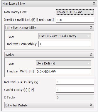
Non-Darcy Flow is used to improve the computation of connection factors for cells penetrated by well pipes. A pre-computed D-factor can be set using User Defined D-factor. Selecting the option Compute D-factor displays the following set of properties:
- Inertial Coefficient
- User Defined – Beta-factor in Forcheimer units
- Use Fracture Beta Factor – Extract beta factor from the fracture template at the well intersection location. For transversal fractures, the conductivity is computed from the geometric average of fracture cells intersected by the fracture perforation length.
- Effective Permeability
- User Defined – Defines the permeability Ke in milliDarcy in the property Effective Permeability
- Use Fracture Conductivity – Extract conductivity from the fracture template at the well intersection location and scale with Relative Permeability. For transversal fractures, the conductivity is computed from the weighted average of fracture cells intersected by the fracture perforation length.
- Width
- User Defined – Defines the width of the fracture
- Use Fracture Width – Extract width from the fracture template at the well intersection location. For transversal fractures, the width is based on the weighted average of fracture cells intersected by the fracture perforation length.
- Relative Gas Density
- Gas Viscosity
- D Factor – Displays the computed value of the D factor. NOTE : For transversal fractures, the computed D factor is scaled by 1.2 to compensate for a different flow model
- D Factor Details – Displays the value of variables used to compute the D factor
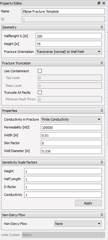
Ellipse Fracture Template
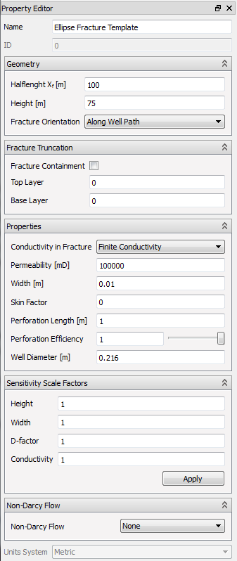
- Name – User name of this particular fracture template
- Geometry
- Halflength Xr – Half the width of the ellipse
- Height – The height of the elliptical fracture
- Fracture Orientation – See above
- Fracture Truncation – See above
- Properties – The availability of these options depend on the Fracture Orientation and the Conductivity in Fracture setting
- Permeability – A constant permeability inside the fracture (Used to calculate conductivity in the fracture)
- Width – Crack width (Used to calculate conductivity in the fracture)
- Sensitivity Scale Factors – See above
- Non-Darcy Flow – See above
Stimplan Fracture Template
StimPlan fracture templates imports XML output from the StimPlan software. These XML files contains results from a simulated hydraulic fracture, describing both geometry, varying crack width, resulting conductivity etc. as time varying quantities. Both symmetric and asymmetric StimPlan fracture templates are supported.
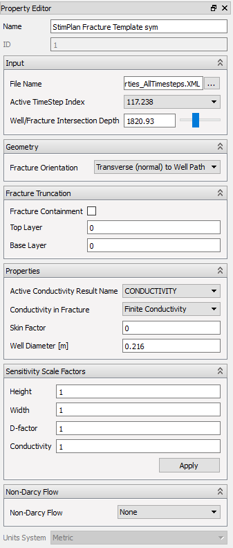
- Name – User name of this particular fracture template
- Show StimPlan Mesh – Show or hide the mesh lines on the fracture in the 3D View
- Input
- File Name – Path to the imported StimPlan XML-file
- Active Time step Index – Time step in the StimPlan simulation to use for transmissibility calculations and visualization
- Well/fracture Intersection Depth – The position of the fracture along the well path as MD.
- Geometry
- Fracture Orientation – See above
- Fracture Truncation – See above
- Properties
- Conductivity Scaling Factor – Scale the overall conductivity to do sensitivity studies.
- Sensitivity Scale Factors – See above
- Non-Darcy Flow – See above
Fracture Instances
Instances of fractures can be created along well paths by right clicking the well pipe in the 3D view, or the corresponding items in the Project Tree.
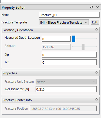
- Name – User editable name
- Fracture Template – Select the fracture template to use for this fracture. Click the Edit shortcut next to the template selection list to go directly to modify the selected template.
- Location/Orientation
- Measured depth Location – The measured depth
- Azimuth – Azimuth orientation of fracture.
- Dip – Dip of fracture plane
- Tilt – Rotation of fracture about its plane normal
- Properties
- Fracture Unit System – Read only display of the units used for the current template
- StimPlan Time Step – Displays the time step used by the template
- Perforation Length / Perforation Efficiency / Well Diameter – These values are copied from the new template when selecting a different one. See Common Fracture Template Options
- Fracture Center Info – This group displays info on where the center of the fracture is positioned. The center is defined to be where the well path intersects the fracture.
Multiple Fracture Creation
In some cases the user wants to create a number of fractures on one or more well paths. Doing this by creating one by one fracture can be very error prone and time consuming. To ease this task, ResInsight has support for creating several fractures in one operation.
Select one or more well paths in the project tree, right click and select Create Multiple Fractures from the right-click menu. Then the Create Multiple Fractures dialog appears. In this dialog, the user defines where fractures will be created on the selected well paths. Different fracture templates and spacing can be used for different K layer ranges in the grid, by adding new options lines to the table. To edit an option line, double click the field to edit. Adding and deleting option lines are done by right clicking the table.
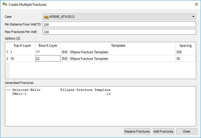
- Case – Current grid case
- Min Distance From Well TD – Minimum distance from well tip for created fractures
- Max Fractures Per Well – Maximum number of fractures to create per well
- Options
- Top K Layer – The topmost K layer to add fractures to
- Base K Layer – The bottommost K layer to add fractures to
- Template – The fracture template used in the specified K layer range
- Spacing – The distance between each fracture in the K layer range
- Generated Fractures – Output information to the user. Shows number of fractures that will be created on each selected well path
- Replace Fractures – Press this button to delete all existing fractures on the selected wells before creating new fractures
- Add Fractures – Press this button to add the new fractures to all selected wells (not deleting existing fractures)
The Create Multiple Fractures function is also available as a CommandFile command. See the CommandFile section