Intersections
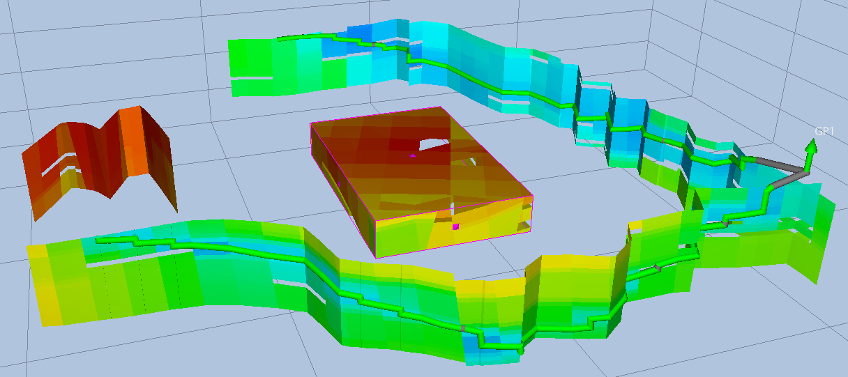
Intersections are cross sections of a grid model that cut the grid in various ways to display grid cell values. There are two main types of intersections:
-
Intersection: is defined by a piece-wise linear curve and a direction of extrusion. The curve can be either a simulation well, a well path, a user defined polyline, or a user defined line. An intersection can also be shown in a separate 2D Intersection View.
-
Intersection Box: can be used as a box cutting grid cells or collapsed to a restricted axis aligned plane.
Structural uncertainty can be visualized on intersections as described in Ensemble Surface.
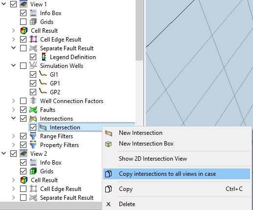
All types of intersections are stored in the folder Intersections of a View. An intersection may be copied to other views by the menu option Copy intersections to all views in case in the right-click menu.
Curve Based Intersections
There are four types of curve based intersections: Well Path, Simulation Well, Polyline, and Azimuth and Dip. Azimuth and Dip differs from the other three curves, as it is defined just by one straight line. It is called Azimuth and Dip because the plane’s extrusion direction can be defined by the two angles.
Any of these intersections can be created by activating
 New Intersection from the right-click menu of the Intersections item in the Project Tree. They can also be created from the right-click menu in the 3D view, as described below.
Info
To be able to see the intersections in the 3D view, the grid cells can be hidden by disabling the Grids item in Project Tree or activating the Hide Grid Cells toolbar button.
Common Curve Based Intersection Options
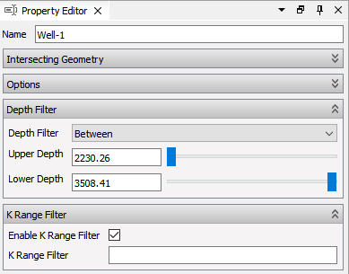
The property panel of a well path based intersection is shown below:
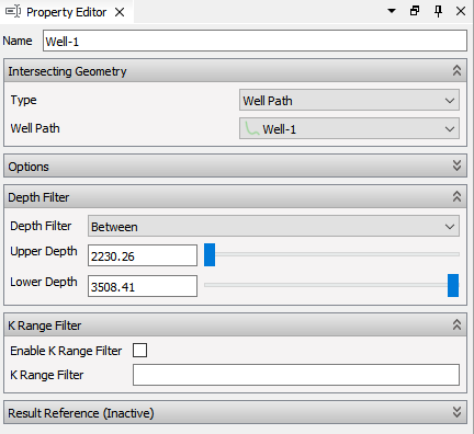
- Name – Automatically created based on the item specifying the intersection. The user can edit the name, but it will be updated if you change well or well path.
- Intersecting Geometry – Options to control the curve used for the cross section dependent on the type of intersection.
- Depth Filter – Controls the depth/z-range for visible geometry. Can be controlled from the Intersections folder object.
- K Range Filter – Controls the visible K slices. Can be controlled from the Intersections folder object.
Advanced options
- Direction – Horizontal, vertical or defined by two points.
- Extent Length – Defines how far an intersection for well path or simulation Well is extended at intersection ends.
- Show Inactive Cells – Controls if inactive cells are included when creating intersection geometry.
Direction is used to extrude the curve in the defined direction, and thereby create a set of planes. Horizontal implies the start and end point of the curve is used as a baseline, and the horizontal direction is thus perpendicular to that line. By Defined by two points, the user can define the direction based on any two points. The direction from the first to the second point defines the extrude direction.
Well Path Intersections
A new Well Path intersection can be created by right-clicking the well path in the 3D view or in the Project Tree.
A new Simulation Well intersection can be created by right-clicking the simulation well in the 3D view or in the Project Tree.
When a simulation well intersection is created, the source simulation well can be changed by using the Simulation Well selection combo box in the Property Editor.
If the well contains more than one branch, the intersection geometry will be created for the selected branch in the Branch combo box.
Polyline Intersection
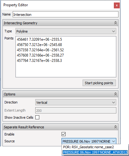
A new Polyline intersection can be created from the right-click menu in the 3D view. Then, by left-clicking on reservoir geometry, a polyline is created. The points are added to the point list in the Property Editor.
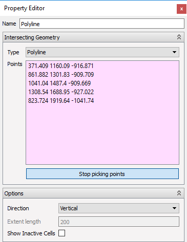
- The background color of point list is light pink when additional points can be picked in 3D view.
- To finish adding points, click button Stop picking points (color of point list turns white).
The points in the list can be deleted and edited using the keyboard. To append more points (by clicking in the 3D view), press button Start picking points again.
The point list can be copied to clipboard using CTRL-C when in keyboard focus. A new list of points can be pasted into the point list by using CTRL-V.
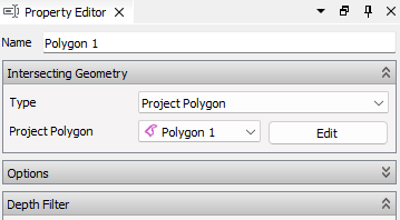
Polygon Intersection
A polyline or polygon intersection can also be based on a Polygons in the project. The polygon is then used as the polyline. This is done by selecting the polygon in the Property Editor.
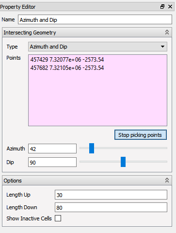
Azimuth and Dip
A new Azimuth and Dip intersection can be created from the right-click menu in 3D view. Then, by left-clicking two points on reservoir geometry, a single line is created between the first point, and the second point projected down to the plane with same z-value as the first point. The two points are added to the point list in the Property Editor.
- The background color of point list is light pink when additional points can be picked in 3D view.
- To finish adding points, click button Stop picking points (color of point list turns white).
The points in the list can be deleted and edited using the keyboard. To append more points by clicking in the 3D view, press button Start picking points again.
The points in the list can be copied to clipboard using CTRL-C when in keyboard focus. A new list of points can be pasted into the point list by using CTRL-V.
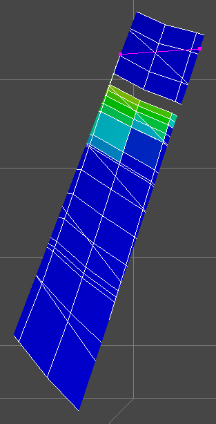
When two points are picked, a plane between the points will appear in the 3D view with a 90 degrees Dip, and the Azimuth angle calculated from the two points. The two angles can be edited in the Property Editor of the intersection:
- Dip: angle between the horizontal plane and down.
- Azimuth: angle between North and the plane. Changing azimuth will rotate the plane about the first point picked in 3D view.
The length of the plane can also be set manually in the Property Editor.
- Length Up is the distance from the user defined horizontal line, to the top of the plane intersecting the model.
- Length Down is the distance from the user defined horizontal line, to the bottom of the plane intersecting the model.
2D Intersection Views
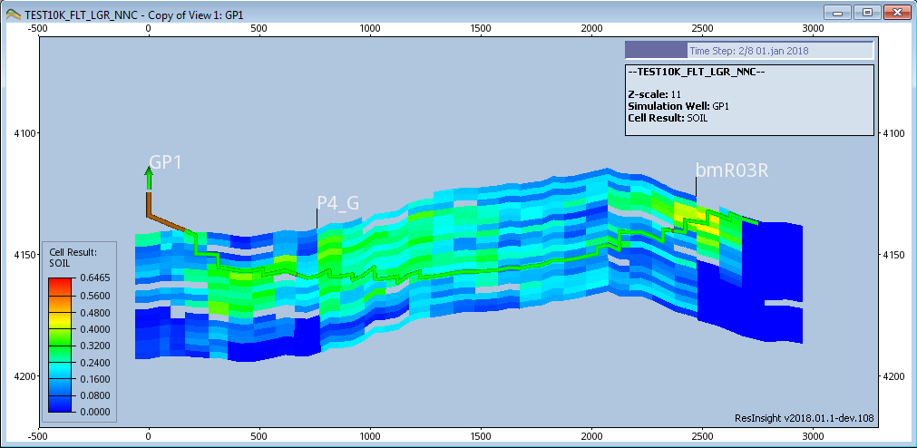
A 2D Intersection View displays the intersection in a separate 2D view along with the defining curve. The intersection and the defining well path, simulation well or polyline is flattened to make it easier to see the intersected grid and how the well traverses it.
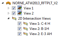
Each of the curve based intersections have a corresponding 2D Intersection View. Management of these views are automatic. They will be created and deleted along with the intersection.
A 2D Intersection View is shown either by right clicking an intersection and select Show 2D intersection View or by checking its entry in Project tree.
Scales along the edges of the view show the depth and the horizontal length of the intersection. The length is measured from the start of the wellpath or the well head of a simulation well.
The view is mostly controlled by the options in the 3D view where the intersection is defined. There are, however, some independent controls, like drawstyle, timestep and Z-scale:
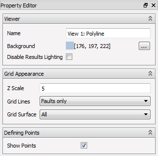
- Viewer
- Name – User editable name of view. The default name combines the name of the origin view and intersection name.
- Background – Color of the viewer background
- Disable Results Lighting – Toggle the light effect. When turned off, the colors are easier to compare with legend, but carry no visual cue to visualize 3D shape. The effect is tiny on 2D Intersection Views.
- Grid Appearance – Controls the drawstyle of the grid geometry
- Z Scale – Scales the view in Z(depth) direction to make slim K-layers easier to see
- Grid Lines – Controls what mesh lines to draw
- All – All mesh lines are drawn
- Faults Only – Only mesh lines associated with faults are drawn
- None – Mesh lines are not drawn at all
- Grid Surface – Controls what grid surface geometry to draw
- All – All grid faces are drawn
- Faults Only – Only faces that are included in a fault is drawn
- None – Do not draw any faces
- Defining Points
- Show points – Toggle the display of the defining points for Polyline or Azimuth and Dip intersections.
These options are similar to the options for a regular 3D view (See View Properties )
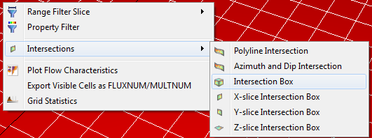
Intersection Box and Intersection Planes
A new Intersection Box or Intersection Plane can be created from the right-click menu in the 3D view or the right-click menu in the Project Tree.
The following list describes the properties for an Intersection Box:
- Name – Automatically created based on the item specifying the intersection
- Box Type – Box or x-plane, y-plane or z-plane
- Show Inactive Cells – Controls if inactive cells are included when creating intersection geometry
- X Coordinates – Coordinates for x range
- Y Coordinates – Coordinates for y range
- Depth – Coordinates for depth range
- XY Slider Step Size – Defines incremental changes for slider when XY values are changed (default value 1.0)
- Depth Slider Step Size – Defines incremental changes for slider when depth values are changed (default value 0.5)
Direct interaction in a 3D view is activated when Show 3D manipulator is pressed. Handles are displayed at the sides of the intersection object, and interactive modification is done by dragging a handle in the 3D view.
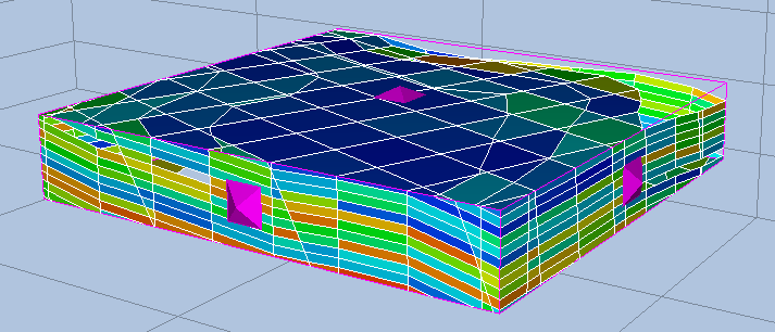
Depth and Range Filter
An intersection can be visually filtered, i.e. partly hidden from display, by employing a user defined Depth Filter. Depth filtering is performed by selecting an intersection in Project Tree and setting Depth Filter properties in Property Editor:
- None: no depth filtering
- Above: show above the specified Depth
- Below: show below the specified Depth
- Between: show between the specified Upper Depth and the specified Lower Depth
An intersection can be also be visually filtered by a user defined K Range Filter. K Range filtering is performed by enabling K Range Filter of an intersection. The filtering is defined using a text string, i.e. “5,10-15,20:3”, see Advanced Text Input for details.
Filter Options for all Intersections
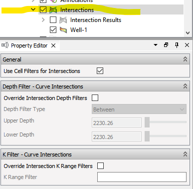
The filtering of all intersections can be controlled when selecting the Intersections folder object. Activating these options will override the settings defined locally on each intersection.
Similar options can also be activated for Faults.
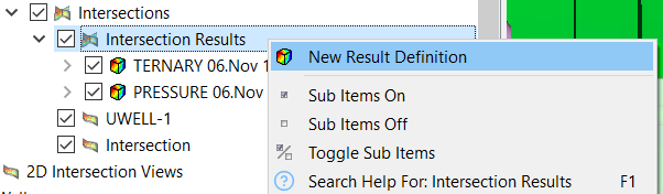
Intersection Results
To select a simulation result to display on an intersection, right-click Intersection Results in Project Tree and select New Result Definition.
By selecting a specific Intersection Result, the Property Editor allows to specify case, type or position etc depending on whether the result stems from a reservoir simulation case or a Geomechanical case.
The next step is to select an Intersection in Project Tree and define Result Reference. In the example below, available sources are the two Intersections Results of previous figure, one of which stems from a geomechanical case and the other from a reservoir simulation case.