Create Well Paths
ResInsight lets the user create new/custom well paths by clicking in the 3D view. A self created well path will behave the same way as an imported well path.
Building a multilateral well path
Building a well path
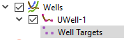
- Right click Wells in the project tree
- Select Create Well Path in the right-click menu. A new well node and a well targets node are created
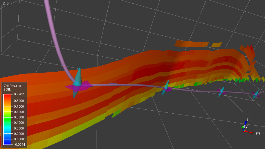
- Click in the 3D view on locations where the well path should pass (well path targets)
- When finished placing targets, click on “Stop Picking Targets” in the property editor
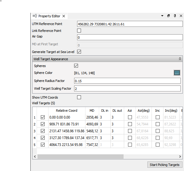
Well targets property editor fields:
- UTM Reference Point - Reference point. Defaults to the first target point clicked.
- Link Reference Point - All wells with this option checked will be moved as a group.
- Air Gap - Specify Air Gap, i.e. distance from Rotary Kelling Bushing to sea surface. Applies to well path export only.
- MD at First Target - Defines the measured depth at the first defined well target.
- Generate Target at Sea Level - Automatically create a target at sea level based on a reasonable well path from reservoir to sea level
Well Targets Appearance
Controls the visibility and appearance of spheres at well target locations in addition to 3D interaction handles. The 3D interaction handles will be visible only when the Well Target object is selected, but the spheres will be always be visible if enabled.
Well Targets
List of all defined well targets. The editor will have a contrast background color when in picking state.
- Relative Coord - Target position relative to reference point. UTM Coords can be displayed using a checkbox option above the table.
- MD - Measured depth along the well path.
- DL in - Dog leg inwards [degrees/30m].
- DL out - Dog leg outwards [degrees/30m].
- Azi (deg) - Azimuth. Y axis is 0 degrees. If the Azi checkbox is ticked, the user can provide a fixed value for Azimuth.
- Inc (deg) - Inclination. Z axis is 0 degrees. If the Inc checkbox is ticked, the user can provide a fixed value for Inclination.
The other columns defined by the “Est”-prefix displays the result of dog leg and direction values produced by the well path geometry estimation algorithm.
A well path defined by well targets may be edited by either editing coordinates in the property editor or clicking and dragging targets in the 3D view.
Well Target Interaction Operations
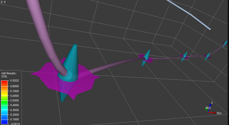
When the well target handles are active in the 3D view, the following operations are possible when pressing left mouse button on well target handles:
Clicking and dragging the blue part of a target, it can be moved along the Z axis only. Clicking and dragging the magenta part of a target, it can be moved horizontally in the XY-plane.
| User Interaction | Description |
|---|---|
| Mouse Move | Modification of a single target |
| Mouse Move + CTRL | Modification of all well target on selected well (laterals excluded) |
| Mouse Move + CTRL + SHIFT | Modification of all well targets (laterals included) |
Well Path Duplication
To duplicate an existing well path, select Duplicate from the right-click menu of a well path in the Project Tree or right-click on the well path geometry in the 3D view. This operation will create a new well path with a set of well targets.
The full geometry of the new well path is an estimate of the source well path, so the geometry might differ slightly.
Starting well path at a fixed position
The toggle Generate Target at Sea Level is on by default. If the well path is supposed to start at a predefined location at the sea level, the following procedure can be used:
- Right click Wells in the project tree
- Select Create Well Path in the right-click menu. A new well node and a well targets node are created.
- Clear Generate Target at Sea Level
- Right-click in the pink well target area, and select Insert new Target above
- In the UTM Reference Point field, enter the predefined UTM coordinate (usually, the depth is set to 0.0 for sea level)
- Continue clicking on geometry in the 3D view to add more well targets and make sure the first well target is defined by [0.00 0.00 0.00] to make sure the first target is located at the predefined UTM reference position
Well Plan
A well plan can be displayed by selecting Show Well Plan from the right-click menu of a generated well path.